| Author |
Message |
|
stefanberndtsson
Joined: Wed Jul 02, 2014 9:36 pm
Posts: 32

|
I'm currently messing around with making a Z80 construction work on a breadboard. Since this has now reached a stage slightly higher than just testing things, it's time to describe it a bit (as requested by Ed :)). The setup is fairly simple: Z80 CPU 128kB SRAM (64kB usable, high bit is grounded) Arduino Nano (bootstraping and I/O control) 2x MCP23S17 (I/O expander on SPI-bus for address/data bus access for the Arduino) 74LS74 (used for fast-trig of the WAIT pin on I/O-requests, because the Arduino can't respond fast enough on its own. Concept stolen from Ben Ryves ( http://www.benryves.com)) The initial boot process is handled by the Arduino. It pulls the RESET low immediately to halt the Z80. It then uses the MCP:s to write Z80-code to the SRAM, which is currently a small program (a loop writing "Hello World!" over and over to serial). Once the Arduino is done, it puts all pins into high impedance (makes them inputs), and releases the RESET pin. Now that the Z80 is running the show, it uses OUT (1),A to send a character. This request is first caught by the CLR-pin of the 74LS74, causing it to immediately put the Z80 into WAIT state. At the same time an interrupt is triggered in the Arduino, which now samples the address and data bus to get the I/O-port (1) and the byte sent, and just forwards that byte to the Arduino Serial output. When done, it triggers the PRE-pin of the 74LS74 which releases the WAIT state and things move on. One lesson though. Do not leave BUSREQ floating. It can cause some weird hangs. :) (I just spent several hours trying to find out why things wouldn't work reliably) At the moment all Z80 code is compiled into an array in the Arduino code, but the plan is to either load it from SD-card or even more preferably be able to load via Ethernet. Some sort of input system would be useful as well. I might use an internal Atari ST keyboard for that, since it's pretty much just a normal TTL-serial connection anyway, and I have some spares. I guess that's the state for now. We'll see how it goes. Some images might be appropriate too. The expected mess of wires:  Lots of "Hello World!" (the number is just a output row counter generated by the Arduino):  ...and the logic analyzer: 
|
| Sat Jul 05, 2014 8:49 pm |

|
|
|
BigEd
Joined: Wed Jan 09, 2013 6:54 pm
Posts: 1782
|
I like this very much! I've been thinking about something similar using a 65816, so it's great to see that you have this working. Using an arduino as boot source and I/O system seems like a very good way to proceed: no need to program EPROMS, but you have a genuine retro address and databus to play with. USB connection for free.
Cheers
Ed
|
| Sun Jul 06, 2014 8:03 am |
|
|
|
stefanberndtsson
Joined: Wed Jul 02, 2014 9:36 pm
Posts: 32
|
This evening was spent trying (and failing) to get an AY-3-8910 (PSG sound chip) hooked up to the thing. Since it's running directly on the address/data bus and not going through the Arduino, I had to map I/O-space a bit. The Arduino now gets all requests from 0x00 to 0x7F, and ignores all others. The AY is mapped on 0xA0-0xA2 (mapping chosen because that's where it's put in the MSX I/O-space, and it seemed reasonable to copy a standard.
For the Arduino that mapping is simply OR:ing A7 and IORQ together instead of just using IORQ as I did before.
The mapping of I/O-space for the AY is accomplished with a 74HC540 inverting the proper bits of the address lines, and then feeding into a 74LS30 (8-input NAND), resulting in a Chip Select which is in turn NOR:ed with the IORQ from the Z80 and AND:ed with the low address bits for controlling the AY bus control pins.
To me it looks like everything is being fed into the AY, but I get no analog output, so I'm sure I'm just missing something obvious. :)
...that's it for today.
|
| Sun Jul 06, 2014 10:39 pm |
|
|
|
BigEd
Joined: Wed Jan 09, 2013 6:54 pm
Posts: 1782
|
First thing - are you running slow enough for those 4 gate delays to produce the signal you need?
Second thing - have you worked through all the inversions and active-low signals to be sure you're producing the right answer? (It's an obvious point, and I don't intend to insult, but it's one of those check, double-check and then check again kind of things!)
Cheers
Ed
|
| Mon Jul 07, 2014 8:16 am |
|
|
|
stefanberndtsson
Joined: Wed Jul 02, 2014 9:36 pm
Posts: 32
|
Oh yes. I'm currently running at about 5kHz, so gate propagation isn't really much of an issue here. :)
As for the logic, I have the logic analyzer hooked up, and things seem right. I've done this before using an Arduino to talk to the AY, where I had other weird troubles (for some reason the AY datasheet specify the register numbers in octal notation, but that's not the issue here). I'll hook the Arduino into the IORQ line and see if I can produce output without the Z80 being involved. I also have some spare AY's in case there just happens to be something wrong with this one.
|
| Mon Jul 07, 2014 10:34 am |
|
|
|
BigEd
Joined: Wed Jan 09, 2013 6:54 pm
Posts: 1782
|
Does the sound chip have registers that you can write to and read back? If so, you can see if it's connected OK as a peripheral, independent of whether it can make sounds.
|
| Mon Jul 07, 2014 11:36 am |
|
|
|
stefanberndtsson
Joined: Wed Jul 02, 2014 9:36 pm
Posts: 32
|
Indeed it does have registers that can be read back. So I wrote an Arduino program that talked to the AY (using the same data-paths as the Z80), writing registers and reading them back. All I got was the register number back, not the content. Something was obviously wrong with the logic. In fact there was an error, but that was minor at kHz speeds, and I don't think it would've been apparent until I'd pushed the Z80 up to MHz speeds. Anyway, with that fixed, it should work, right? Well, it didn't. Still the same thing. The logic analyzer shows everything working fine, with the single exception of the return value for the requested register still being the register number, not the content. Darn (ok, I might've said something slightly more explicit than that). Finally I just figured I'd swap AY with another one. Sure enough, everything was read back just fine. Analog outputs working nicely as well. My original short Z80-program also did its job.  
|
| Mon Jul 07, 2014 9:28 pm |
|
|
|
BigEd
Joined: Wed Jan 09, 2013 6:54 pm
Posts: 1782
|
Good news! I suppose this supports the idea that you're better off if you get 2 or 3 of each chip.
Cheers
Ed
|
| Tue Jul 08, 2014 8:19 am |
|
|
|
Dr Jefyll
Joined: Tue Jan 15, 2013 5:43 am
Posts: 189
|
Just a reminder: sometimes removing a "defective" chip and then re-installing it will produce success. That's because the problem was caused by faulty contact between the pins and the socket, and removing & re-installing the chip freshens up that connection. So, if you haven't already, try re-installing the original chip and giving it another chance to work. Quote: Do not leave BUSREQ floating. It can cause some weird hangs.  It's best not to leave any MOS or CMOS inputs floating. (This applies to logic as well as CPUs & peripheral chips.) The input impedance is extremely high, and that means that, left unconnected, they won't necessarily drop to ground as one might expect. Static fields, invisible contamination on the board and the phase of the moon all are sufficient to drive (C)MOS inputs amok. If BUSREQ is the only one of several floating inputs that caused you trouble, that's because Murphy is holding the others in reserve to torment you some other day!  Don't wait for more punishment -- tie unused inputs high or low. -- Jeff ps - Congrats on the project, BTW!
Last edited by Dr Jefyll on Tue Jul 08, 2014 1:46 pm, edited 1 time in total.
|
| Tue Jul 08, 2014 1:41 pm |

|
|
|
stefanberndtsson
Joined: Wed Jul 02, 2014 9:36 pm
Posts: 32
|
Dr Jefyll wrote: Just a reminder: sometimes removing a "defective" chip and then re-installing it will produce success. That's because the problem was caused by faulty contact between the pins and the socket, and removing & re-installing the chip freshens up that connection. So, if you haven't already, try re-installing the original chip and giving it another chance to work.
It's best not to leave any MOS or CMOS inputs floating. Their input impedance is extremely high, and that means that, left unconnected, they won't necessarily drop to ground as one might expect. Static fields, invisible contamination on the board and the phase of the moon are all sufficient to drive (C)MOS inputs amok. If BUSREQ is the only one of several floating inputs that caused you trouble, that's because Murphy was holding the others in reserve to torment you some other day! :twisted:
Both good points. I'll do the AY-swap in a bit and see. As for the BUSREQ, it wasn't floating before I hooked up IORQ to the Arduino, I figured I'd do the same with BUSREQ for when I'd need it sometime later. Forgot to set the pin to output and/or pull it high. I haven't ripped the other pins yet, so they're still in the proper configurations. Thanks. :)
|
| Tue Jul 08, 2014 1:46 pm |
|
|
|
stefanberndtsson
Joined: Wed Jul 02, 2014 9:36 pm
Posts: 32
|
Dr Jefyll wrote: Just a reminder: sometimes removing a "defective" chip and then re-installing it will produce success. That's because the problem was caused by faulty contact between the pins and the socket, and removing & re-installing the chip freshens up that connection. So, if you haven't already, try re-installing the original chip and giving it another chance to work. I've been messing with lots of other stuff today, but I did give reseating a go, and it didn't help. The chip acts as if it can't latch the data from registers when reading them, and instead just puts whatever is in the latch to the data bus (which of course is the register number, since that's the last thing that was requested before the read). Probably a break internally somewhere. Good thing I have lots more of them. :)
|
| Tue Jul 08, 2014 10:54 pm |
|
|
|
stefanberndtsson
Joined: Wed Jul 02, 2014 9:36 pm
Posts: 32
|
Haven't been at it for a couple of days, but since the site is back up, it's time to fill in the bits that have been done. The Z80 is now hooked up to a Yamaha V9958 video chip with RGB output to a Commodore 1084 monitor. As with the audio, this is also located at the I/O-ports chosen by the MSX standard (0x98-0x9b). The V9958 is a nice chip. Fully software compatible with the TMS9918/9928/9929 and the V9938 (almost, the 9938 has support for mouse and lightpen which was removed in 9958). At the moment I'm only messing with simple text modes, but it's capable of displays of up to 512x212 in 16 colours of 512 or 256x212 in 19268 colours (weird number, but that's the number of unique RGB values it outputs from an internal component like display). With a 64pin DIP with 70mil pitch I needed an adapter to fit into breadboards, and with the width that got me, I had to use two, and a third for the 128kB DRAM used as video memory. So I'm now up to 7 breadboards for the build, and I can no longer change the power supplies through them without far too big a voltage drop, so I had to pretty much feed each board directly. ...and here's the visual evidence. :)  Simple text outputted by the Z80 using the font ripped out of an Atari ST ROM-file.  The whole lot at once, with lots and lots of probes :) 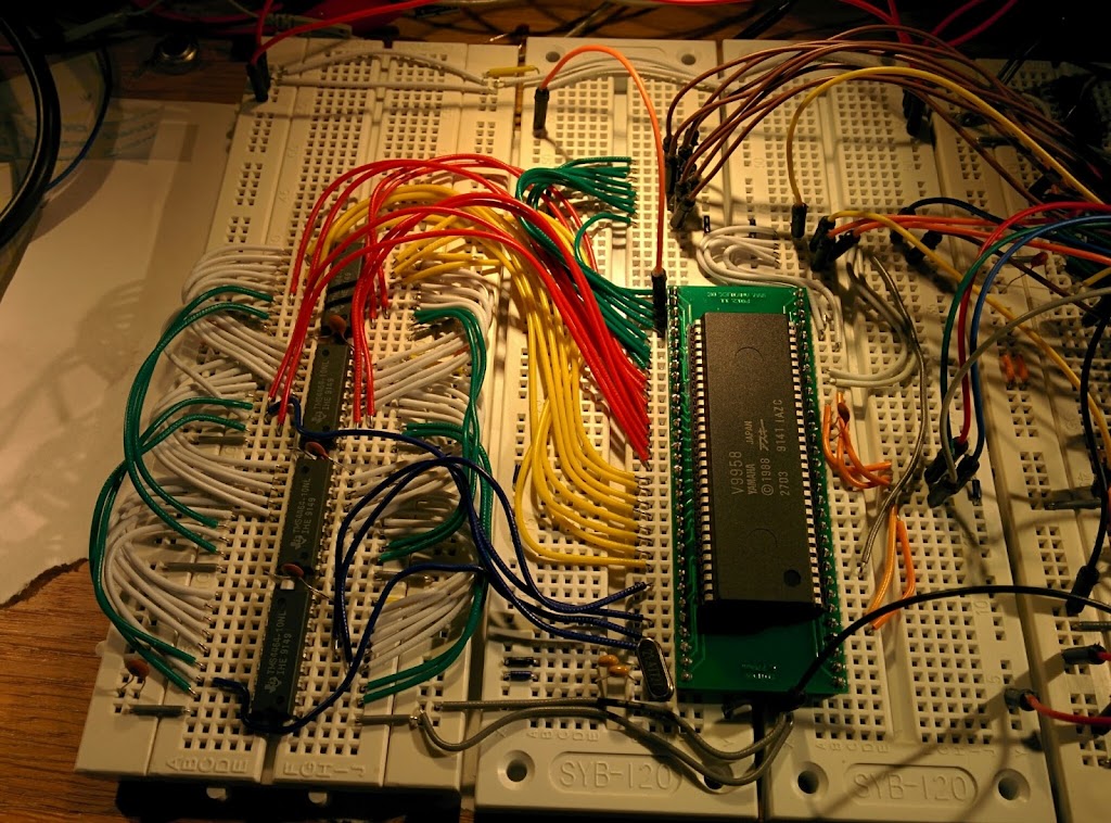 Closeup of the VDP part, before the logic analyzer got its probes on it. Next part, that's been initiated already, is to interface an internal Atari ST keyboard with the Arduino for use as input device. The Atari ST keyboard uses a simple 7812.5 baud TTL-level serial connection (a quarter of the MIDI frequency, since the ACIA for MIDI in the Atari ST is fed by the same clock as the ACIA used for the keyboard). A small initial reset sequence, and it just spits out scancodes for press and release events. It also handles two joystick ports which can be received the same way. Very convenient and simple to implement.
|
| Thu Jul 17, 2014 9:08 pm |
|
|
|
stefanberndtsson
Joined: Wed Jul 02, 2014 9:36 pm
Posts: 32
|
Next step with basic input support is now in place. It turned out to be far more complicated than I'd expected it to be, and I had to restructure things quite a bit around the data bus access from the Arduino. The concept of the Arduino part of the I/O system is that when the Z80 issues an IORQ, it immediately triggers the WAIT pin (via a 74LS74). The Arduino then reads the lower half of the address bus to get the I/O port number, and then either reads the data bus if it was an OUT instruction or writes to the data bus if it was an IN instruction causing the IORQ. OUT instructions worked fine (I keep the Arduino side of the data bus in high impedance anyway). Writing a reply however, did not work properly. My Arduino setup uses MCP23S17 (two of them) to access address and data. These are SPI-controlled I/O-extenders. Doing things on them are far from instantaneous. This means I write the data bus content, then release the WAIT pin, and after that, I put the MCP part of the data bus back into high impedance. Unfortunately this is too slow, so the Z80 manages to read the next instruction with my data still on the bus, causing slight issues :). To resolve all this, I put a 74LS245 in between the MCP and the data bus, which needed quite a bit of extra logic to trigger the right way. All in all, the Arduino part of the data bus is now isolated from the rest of the bus unless it's needed for I/O (or during initial setup). The input device is, as mentioned before, an internal Atari ST keyboard, connected to a SoftSerial connection on the Arduino. The Arduino translates the scancode into ascii which it keeps in a buffer. The Z80 can ask if there is anything waiting and ask what is in there. To get the proper output, I wrote a very very very simple terminal thingie for the Z80 that can clear the screen, setup font and other things, output characters and strings and move and keep track of the cursor, and scroll the screen if it reaches the bottom. The image below shows the 40 column mode, now with the MSX font, since it's constructed to fit (6x8 characters in 8x8 matrices). There is also an 80 column mode working. 
|
| Sat Jul 19, 2014 8:13 pm |
|
|
|
stefanberndtsson
Joined: Wed Jul 02, 2014 9:36 pm
Posts: 32
|
It's too hot to actually sit in a room full of heat generating equipment and the breadboard construction is a bit messy now, with everything being stored in my head. Therefor I've begun drawing up schematics on (some of) the modules involved. Every module has a 2x25pin header with all the address, data and control lines from the Z80. I figured I'd use a 2x25pin one so that I can connect them together with an old SCSI cable later on. This means the CPU and RAM modules are insanely simple. It's just the connector, one IC and a bypass cap each (links below). The last one I've done so far is the Video module with the Yamaha V9958. That one is a bit more complex with the VDP itself, three logic IC's for address and signal decoding, and four DRAM's. All with their own bypass caps of course. Left to do so far is the Arduino module and the Audio module. Everything is done in KiCAD, which with the new (although somewhat buggy and crashy) OpenGL based PCBnew is rather nice to use now. Links to PDF's: CPU Module64kB Memory ModuleV9958 Video Module
|
| Wed Jul 23, 2014 3:36 pm |
|
|
|
stefanberndtsson
Joined: Wed Jul 02, 2014 9:36 pm
Posts: 32
|
While I was putting down the schematics of the Arduino module, I started thinking about the 7474 method of handling the WAIT pin. Something didn't seem quite right with it, and I've now changed it a bit by inverting things a bit and using a 4013 instead.
I have a signal I call AVRCS, which is OR(IORQ,A7), which means it's low only when both A7 is low and IORQ is low (I/O-request to ports 0x00-0x7f). This is the signal the Arduino module can use to signal that it's being accessed as an I/O-device (Active Low just like IORQ).
Basically, it worked like this with the 7474:
1. AVRCS goes low
2. CLEAR-pin of the 7474 causes the Q to go low as well. this Q is connected straight over to WAIT, causing the Z80 to wait immediately.
3. The Arduino can now probe the address/data bus for relevant data, knowing that the Z80 is just hanging waiting.
4. Once the Arduino is done, it triggers the SET-pin of the 7474.
5. Given that the 7474 is a D-FlipFlop specified to handle both SET and CLEAR active at once, this causing Q to go high again, releasing WAIT.
6. Arduino must now wait for AVRCS to go high again, before it can release the SET-pin, otherwise it would go low once more, which wouldn't be right.
Herein lies the issue I have. If the Arduino is just a bit too busy, that last waiting for AVRCS can be slow enough to to miss another I/O-request before it's registered and handled the end of the previous one.
I figured I was only really interested in the falling edge of the AVRCS (the one actually causing the request), but all Flip-Flops I had used positive edge triggering.
My new (and untested solution, so I might be missing something obvious here) is:
1. AVRCS goes low.
2. Pushing this through an inverter, I get /AVRCS which now goes high instead.
3. /AVRCS is actually hooked up to the CLK-pin of a 4013, with DATA connected to Vcc.
4. This change to high on /AVRCS then causes the 4013 to put DATA into Q, and its inverse into Q' (which is now low).
5. Q' is hooked to WAIT, which is now low.
6. Arduino does whatever it needs to do.
7. Once the Arduino is done, it just pulses the RESET-pin of the 4013, forcing Q low, and thereby Q' and WAIT high.
8. The Z80 continues its work and AVRCS is eventually released, but since this causes a falling edge of /AVRCS (rising on AVRCS), this is not changing Q or Q'.
This solution should only require the Arduino to pulse once to release WAIT, and not need any monitoring of signals. So based on this I should be fairly certain I'll catch the next I/O-request as long as my pulse is short enough.
This also means my interrupt pin on the Arduino only needs to deal with falling edges (AVRCS) instead of the change mode and extra check I do now, which should speed things up and make them more reliable.
While writing this, I've realised a few bugs in my schematics, so they need fixing right away. :)
|
| Thu Jul 24, 2014 8:17 pm |
|
|
Who is online |
Users browsing this forum: No registered users and 3 guests |
|
You cannot post new topics in this forum
You cannot reply to topics in this forum
You cannot edit your posts in this forum
You cannot delete your posts in this forum
You cannot post attachments in this forum
|

|
