Last visit was: Sat May 23, 2026 4:29 pm
|
It is currently Sat May 23, 2026 4:29 pm
|
GF-RV16 - an experimental 16-bit RISC-V ISA
| Author |
Message |
|
oldben
Joined: Mon Oct 07, 2019 2:41 am
Posts: 928

|
What are your thoughts on memory expansion over 64Kb?
What about a operating system?
Many 16 bit computers of the 70's,had a 8" floppy for IO, thus you had a rather primitive OS,
like CP/M or OS/8 (PDP-8) just because you had no room a better OS or buffers for data.
FAT (12) worked for DOS only because reading word could be at a odd address.
Ben.
|
| Fri Oct 31, 2025 11:44 pm |
|
|
|
gfoot
Joined: Sat Oct 04, 2025 10:54 am
Posts: 25
|
oldben wrote: What are your thoughts on memory expansion over 64Kb?
What about a operating system?
Many 16 bit computers of the 70's,had a 8" floppy for IO, thus you had a rather primitive OS,
like CP/M or OS/8 (PDP-8) just because you had no room a better OS or buffers for data.
FAT (12) worked for DOS only because reading word could be at a odd address.
Ben. I haven't thought much about expansion beyond 64K - I think it's a bit out of scope. For that it would be better to build a full RV32I-based CPU, I think - and there are variants of that which have fewer registers (16) and 16-bit encodings for the most common instructions. But it would need to have wider internal buses to be any use, I think, as loading 32-bit registers through an 8-bit bus would be quite slow. Another option would be something like x86 segmented addressing, or some other form of using two registers together to access a wider span of memory. At the moment I'm taking the lazy option though, which is that the CPU doesn't support it directly and you have to use external banking schemes somehow if you want to attach more memory. For an operating system, so far I have written something basic that just does interrupt handling for asynchronous buffered I/O (well, input at least). I think it will grow organically, so at some point I might make the simulator support some form of file-loading. For actual hardware, if I ever build this, I'll probably use a 6551 for serial I/O (and rewrite the I/O routines to support that), and also probably hook it up to a 6522 for general purpose I/O, which could drive SD cards for example. In my 6502 projects I also often do file I/O through a serial connection to a host PC, and that could work too - the way I see it, all these things that I usually do on 6502-based projects are options that can be used equally well here, and I haven't really decided what shape an actual system would be yet. Unaligned words are an interesting one - initially I accidentally made the simulator support them, so then I had to deliberately break it because it wasn't planned to be supported by the hardware! The issue is fairly minor though - it's just that when reading the high byte of the pair it would be necessary to add (with carry) 1 to the address in the MAR, whereas if I only support aligned reads then I just have to force the bottom bit to be set when reading the high byte, which is just a one-bit OR without requiring a full add. At the end of the day though it would only require a few adder ICs to perform the add, so perhaps I might as well just support this, to make some kinds of code easier to work with. And another way to implement it is to make the MAR actually be a counter rather than a normal register, and increment it directly when performing this sort of operation.
|
| Sat Nov 01, 2025 2:23 am |
|
|
|
gfoot
Joined: Sat Oct 04, 2025 10:54 am
Posts: 25
|
I have updated the web-based simulator ( https://gfoot.github.io/gf-rv16/) with some more features: - New "Machine Code" window shows the source code that was assembled along with the machine code bytes for each instruction, and highlights the currently-executing instruction
- Breakpoints - click to the left of an instruction in the Machine Code window to set or clear a breakpoint, then "Run" mode will stop when it gets there
- Step through by source instruction (skipping to the next pseudoinstruction), machine code instruction (what you'd normally expect) or hardware cycle
- Speed control for Run mode - you can adjust the simulation speed, making it run quickly so that you can see the results sooner, or slowly so you can see what it is doing as it executes the program
|
| Sat Nov 01, 2025 4:27 am |
|
|
|
BigEd
Joined: Wed Jan 09, 2013 6:54 pm
Posts: 1884
|
Very much liking the web emulator! I'm with you that serial I/O is a good starting point, sufficient for lots of fun, and of course one can even implement a filesystem running over serial. Just for interest, we did wonder, discussing this, whether it would be fun to hand-write a Tube ROM and make an Acorn-style second processor with this CPU - could be in C on PiTubeDirect or in Verilog on FPGA. It's been done before, for F100 and OPC at least. (But perhaps not for 65Org16 - yet!) (When I say 'we' it's some combination of me, hoglet, revaldinho, dominicbeesley) The point, of course, is to embed the new core in an existing platform, namely the Beeb's second processor, and Acorn's OS and filesystems. Gives you an APi to keyboard, screen, storage, serial connectivity. Perhaps mainly of interest to people already living in the land of Acorn, or nearby. But it does give ready portability into implementations for emulation, webulation, TTL, FPGA, and PiTubeDirect. A Tube ROM is usually about 2k of binary. You don't need all of it to show proof of life, of course. I've a vague idea one can write some (most?) of a Tube ROM in C, which is of course easier, but not sure where to look for that. And you do need a working C compiler.
|
| Sat Nov 01, 2025 9:36 am |
|
|
|
gfoot
Joined: Sat Oct 04, 2025 10:54 am
Posts: 25
|
BigEd wrote: Just for interest, we did wonder, discussing this, whether it would be fun to hand-write a Tube ROM and make an Acorn-style second processor with this CPU - could be in C on PiTubeDirect or in Verilog on FPGA. It's been done before, for F100 and OPC at least. (But perhaps not for 65Org16 - yet!) I had thought about doing something like that but using Dominic's Blitter board that he leant me... too many years ago. I feel bad because I've had it all this time and not really done anything useful with it. It would require writing more OS code than a Tube ROM would, but I still think it wouldn't take very much code to at least initialise the system and get the basics up and running. I don't have any experience with FPGAs and Verilog so it's not a trivial step, but it could be a good time to learn that. I am also conscious that this design wasn't really meant for that environment, and the compromises I've made were in order to make it practical to implement with less scalable technology, i.e. CPLDs or 74HC logic, so an FPGA implementation might feel unnecessarily restricted - the FPGA might be able to easily support a wider ALU, and a dual-port register file, and then be able to execute most operations in a singe clock cycle. But even if it feels like not the right design for an FPGA, using the FPGA could still be a great way to prove it out more.
|
| Sat Nov 01, 2025 10:47 am |
|
|
|
BigEd
Joined: Wed Jan 09, 2013 6:54 pm
Posts: 1884
|
Ah, yes, good point - FPGA will usually start off larger than your design or project, and it's a bit of a trap that one might to make use of more of it and undertake a bigger project. Self control might be the only answer - or perhaps buy the smallest FPGA you can find!
If you're not already up with verilog and FPGA then this might be an entirely unwelcome sidequest. (But I note in passing that myHDL and amaranth both offer, apparently, ways to work directly from Python.)
On the other hand, FPGAs are a most wonderful way to create fast hardware with very low technical turnaround time - no fabrication step, no wires falling out of breadboards - so as and when you do want to venture in that direction, the rewards are there.
Just watch out for that scope creep...
(On the topic of a Tube ROM, I think implementing just character read and character write would get you quite a long way. Not a great deal more work than a serial interface.)
On the general trajectory of bringing up a new implementation of a new architecture, I'm a proponent of starting with an emulator, and then an assembler. You are of course already well past that point. And most of my preference is based on pitifully little experience, so it's not worth much.
|
| Sat Nov 01, 2025 3:49 pm |
|
|
|
oldben
Joined: Mon Oct 07, 2019 2:41 am
Posts: 928
|
One option is to design a generic interface card, with a FPGA module. This way you could swap out for a bigger FPGA if you need one.
|
| Sun Nov 02, 2025 1:26 am |
|
|
|
DockLazy
Joined: Sun Mar 27, 2022 12:11 am
Posts: 62
|
gfoot wrote: I don't have any experience with FPGAs and Verilog so it's not a trivial step, but it could be a good time to learn that. I am also conscious that this design wasn't really meant for that environment, and the compromises I've made were in order to make it practical to implement with less scalable technology, i.e. CPLDs or 74HC logic, so an FPGA implementation might feel unnecessarily restricted - the FPGA might be able to easily support a wider ALU, and a dual-port register file, and then be able to execute most operations in a singe clock cycle. But even if it feels like not the right design for an FPGA, using the FPGA could still be a great way to prove it out more. A fully pipelined single cycle RV32 processor will use 1-2k LUTS and run at 50-100Mhz. That's possible on a low end FPGA and probably a few hundred lines of Verilog. Depending on your goals that level of performance may, or may not, be a good thing. However I do think FPGAs are great choice as a peripheral controller for a TTL computer. Especially video.
|
| Sun Nov 02, 2025 11:22 am |
|
|
|
BigEd
Joined: Wed Jan 09, 2013 6:54 pm
Posts: 1884
|
Quote: ...the compromises I've made were in order to make it practical to implement with less scalable technology, i.e. CPLDs or 74HC logic... I'm reminded of Arlet's rather splendid quad-CPLD 6502, where it turned out the decomposition into four parts, with limited wires between, worked out rather well. Just possibly a RISCy processor could do similarly, perhaps with more CPLDs. (We should note that availability especially in 5V flavours is quite limited these days, but there are options - AFAICT at least Lattice ispMACH 4000V/B/C and Microchip/Atmel ATF15xx and maybe Intel/Altera Max V.)
|
| Sun Nov 02, 2025 12:33 pm |
|
|
|
gfoot
Joined: Sat Oct 04, 2025 10:54 am
Posts: 25
|
I thought I'd update - in the end I did go down the rabbit hole of learning some VHDL, and writing an implementation for a few simpler modules (the clock generator, program counter, instruction fetch, and some of the decoder). These can work together or in isolation, VHDL has been quite comfortable for that. I also wanted to be able to unit-test them, so I tried a few ways, and then wanted to do a bit more research on what tools are available to make that easier and more standard.
I ended up also wondering if I should use Verilog instead, so learning some of that, and I might reimplement what I've done so far using that just for comparison's sake.
On the testing front, so far it seems like a lot of things are based around either writing a custom testbench in the HDL language itself, or a custom wrapper in either Python or C. I haven't found a lot of information on standardised free tools, just a few names popped up that I'll check out - I was expecting more consensus on this but in general I'm finding that the landscape of free tools is a lot broader than I'm used to, with fewer obvious "peaks". Perhaps it's a case where professionals use the commercial software that matches the devices they intend to use, so that the free software is less distinctive? I need to look into it more but any suggestions are welcome of course!
|
| Fri Nov 07, 2025 1:52 pm |
|
|
|
BigEd
Joined: Wed Jan 09, 2013 6:54 pm
Posts: 1884
|
Ah, an interesting update!
I have personally come down on the side of Verilog, as opposed to VHDL, but of course preferences differ.
I know next to nothing about SystemVerilog, but I have the vague idea that it supports verification better than good old-fashioned Verilog - and, I think, is almost as well-supported.
I believe Verilog models have an ability to write out to a log file, and so it's possible for a model to leave a textual trace of what's happening, such that one can use the usual text processing tools to tally up results. (Maybe thereby exposing internal states, or intermediate states, or code coverage aspects of a particular run.) I vaguely recall that it might even be possible to run interactively, although I might be dreaming.
I think an HDL testbench is a common enough tactic. In my working life, it was normal enough to set up thousands of simulations to be run somewhat in parallel, with semi-random inputs, or biased-random, or directed-random inputs, with post-processing figuring out which cases had been covered. Another tactic is to compare an HDL model's outputs with a C model, or, for example, an HDL model of a simple implementation of a CPU with an HDL model of an aggressively high performance implementation.
|
| Fri Nov 07, 2025 4:04 pm |
|
|
|
gfoot
Joined: Sat Oct 04, 2025 10:54 am
Posts: 25
|
BigEd wrote: I know next to nothing about SystemVerilog, but I have the vague idea that it supports verification better than good old-fashioned Verilog - and, I think, is almost as well-supported. Yes, I saw recommendations for using SystemVerilog for its testability, and it's partly why I've considered learning Verilog too (I understand SystemVerilog has all been merged together now so it's just one modern Verilog - but could be wrong about that). But equally it seems that VHDL has a lot of good features built in to support these things, so switching to SystemVerilog might not have as much benefit as it would if coming from... non-System Verilog? Not sure what to call it! Quote: I believe Verilog models have an ability to write out to a log file, and so it's possible for a model to leave a textual trace of what's happening, such that one can use the usual text processing tools to tally up results. (Maybe thereby exposing internal states, or intermediate states, or code coverage aspects of a particular run.) I vaguely recall that it might even be possible to run interactively, although I might be dreaming.
I think an HDL testbench is a common enough tactic. In my working life, it was normal enough to set up thousands of simulations to be run somewhat in parallel, with semi-random inputs, or biased-random, or directed-random inputs, with post-processing figuring out which cases had been covered. Another tactic is to compare an HDL model's outputs with a C model, or, for example, an HDL model of a simple implementation of a CPU with an HDL model of an aggressively high performance implementation. Partly the way I started learning VHDL was by reference to somebody else's VHDL implementation, which I found on these forums - that one captured VCD files and also used native VHDL code to trace code execution etc. My initial approach was to just use the VCD files, but write a text filter script that converts them into full state tables like those you feed into cupl's simulator, because that's what I'm familiar with - there's enough there that I could just go ahead with that. My filter constrains the output to state changes in specifically chosen columns, and the test harness then requires that output to be identical to the expected result, so it is very much like the kind of test vector based testing I've been doing with WinCupl. It sounds like there are a lot of good avenues for higher level testing (from the software circles I've been part of we'd call it "integration testing" - testing lots of components working together to make sure they are compatible with each other and, in combination, achieve the desired high level effect). I also want to nail down how best to do unit testing though, for each component on its own. Doing it in VHDL directly seems to be largely the done thing, but there's a lot of boilerplate that will cause a tendency to put a lot of testing into one test, rather than having a lot of nice small independent tests. However, VUnit is looking promising as a way to wrap the VHDL testing in such a way that multiple tests can share the same boilerplate, but still run independently. It also supports similar things with Verilog. One of my concerns with writing tests in VHDL itself is also that I'm new to the language and could easily write tests that don't actually test what I think they do! However VUnit has a lot of good practical examples, so that should put me on the right path, it is very appealing.
|
| Fri Nov 07, 2025 7:40 pm |
|
|
|
gfoot
Joined: Sat Oct 04, 2025 10:54 am
Posts: 25
|
Here's an example of what VUnit-based VHDL test code looks like - this is for my program counter, structured very closely to how some of the VUnit examples are structured: Code: library ieee;
use ieee.std_logic_1164.all;
use ieee.numeric_std.all;
library vunit_lib;
context vunit_lib.vunit_context;
library gfrv16;
entity tb_prgcnt is
generic (runner_cfg : string);
end entity;
architecture tb of tb_prgcnt is
signal reset : std_logic := '0';
signal endc : std_logic := '0';
signal c_end : std_logic := '0';
signal c_pcr : std_logic := '0';
signal pcn : unsigned(15 downto 0);
signal bus_b : std_logic_vector(15 downto 0);
begin
main: process is
procedure cycle is
begin
endc <= '0';
wait for 1 ns;
endc <= '1';
wait for 1 ns;
end cycle;
begin
test_runner_setup(runner, runner_cfg);
-- Send a valid reset pulse to initialise the device under test
reset <= '1';
cycle;
cycle;
reset <= '0';
wait for 1 ns;
while test_suite loop
if run("Test that PCN is zero after the reset") then
check_equal(pcn, 0);
elsif run("Test that a clock cycle without c_end asserted has no effect on PCN") then
cycle;
check_equal(pcn, 0);
elsif run("Test that clock cycle with c_end causes PCN to increment by 2") then
c_end <= '1';
cycle;
check_equal(pcn, 2);
elsif run("Test that bus_b is not driven when c_pcr is not asserted") then
-- Converting to a string feels really clunky but I couldn't find a better way
check_equal(to_string(bus_b), "ZZZZZZZZZZZZZZZZ");
elsif run("Test that when c_pcr is asserted bus_b is driven by PC initially zero") then
-- This is asynchronous, so no need to cycle the clock, but we do need a wait.
c_pcr <= '1';
wait for 1 ns;
check_equal(bus_b, 0);
elsif run("Test that PC lags PCN by 2 as PCN advances 2 at a time") then
c_pcr <= '1';
c_end <= '1';
cycle;
check_equal(pcn, 2, result("for pcn"));
check_equal(bus_b, 0, result("for bus_b"));
cycle;
check_equal(pcn, 4, result("for pcn"));
check_equal(bus_b, 2, result("for bus_b"));
cycle;
check_equal(pcn, 6, result("for pcn"));
check_equal(bus_b, 4, result("for bus_b"));
end if;
end loop;
test_runner_cleanup(runner);
wait;
end process;
test_runner_watchdog(runner, 10 ms);
dut : entity gfrv16.prgcnt
port map (
reset => reset,
endc => endc,
c_end => c_end,
c_pcr => c_pcr,
pcn => pcn,
bus_b => bus_b
);
end architecture;
There is still a lot of boilerplate, like with most VHDL code it seems, but at least once it's set up, it is fairly easy to add more tests while adding more functionality to the module that's being tested. The tests are in the "main" process, which starts by sending a reset signal to the device under test and cycling the clock a few times. The individual tests are then listed inside the while loop. I'm not sure why they use a while loop for this, as by default it runs the tests one at a time, restarting the simulation for each test to ensure that side effects from one test don't affect the results of another. Mentally I'm mostly ignoring the while loop, but it's there because that's what the docs say you should do! The individual tests are quite compact, and VUnit provides a range of "check" procedures that can be used for various kinds of tests. I'm still getting to grips with them but they've been effective so far. I'm also finding the output rather noisy - even with the "-q" flag it still prints all this information about which tests it is running and where it's storing the output: Code: gfoot@box:~/riscv/gfrv16/vhdl$ python run.py
Compiling into tb_gfrv16: tests/tb_clock.vhd passed
Compile passed
Starting tb_gfrv16.tb_prgcnt.Test that PCN is zero after the reset
Output file: /home/gfoot/riscv/gfrv16/vhdl/vunit_out/test_output/tb_gfrv16.tb_prgcnt.Test_that_PCN_is_zero_after_the_reset_3bf837d7b2d968dbe976b6f9bdf1bec1660db280/output.txt
pass (P=1 S=0 F=0 T=9) tb_gfrv16.tb_prgcnt.Test that PCN is zero after the reset (0.6 seconds)
Starting tb_gfrv16.tb_prgcnt.Test that a clock cycle without c_end asserted has no effect on PCN
Output file: /home/gfoot/riscv/gfrv16/vhdl/vunit_out/test_output/tb_gfrv16.tb_prgcnt.Test_that_a_clock_cycle_without_c_end_asserted_has_no_effect_on_PCN_795a933826efcc13c2493fa654a9c4011b81b0a1/output.txt
pass (P=2 S=0 F=0 T=9) tb_gfrv16.tb_prgcnt.Test that a clock cycle without c_end asserted has no effect on PCN (0.6 seconds)
Starting tb_gfrv16.tb_prgcnt.Test that clock cycle with c_end causes PCN to increment by 2
Output file: /home/gfoot/riscv/gfrv16/vhdl/vunit_out/test_output/tb_gfrv16.tb_prgcnt.Test_that_clock_cycle_with_c_end_causes_PCN_to_increment_by_2_beaa723a79301c75b78e8b3b1b3c1efbe87de1e7/output.txt
pass (P=3 S=0 F=0 T=9) tb_gfrv16.tb_prgcnt.Test that clock cycle with c_end causes PCN to increment by 2 (0.6 seconds)
Starting tb_gfrv16.tb_prgcnt.Test that bus_b is not driven when c_pcr is not asserted
Output file: /home/gfoot/riscv/gfrv16/vhdl/vunit_out/test_output/tb_gfrv16.tb_prgcnt.Test_that_bus_b_is_not_driven_when_c_pcr_is_not_asserted_7af227bc2be56d4a3b40325520a6a7ff1201027f/output.txt
pass (P=4 S=0 F=0 T=9) tb_gfrv16.tb_prgcnt.Test that bus_b is not driven when c_pcr is not asserted (0.6 seconds)
Starting tb_gfrv16.tb_prgcnt.Test that when c_pcr is asserted bus_b is driven by PC initially zero
Output file: /home/gfoot/riscv/gfrv16/vhdl/vunit_out/test_output/tb_gfrv16.tb_prgcnt.Test_that_when_c_pcr_is_asserted_bus_b_is_driven_by_PC_initially_zero_d6c87d140bde9e27a102cc37e1ad56405629eff5/output.txt
pass (P=5 S=0 F=0 T=9) tb_gfrv16.tb_prgcnt.Test that when c_pcr is asserted bus_b is driven by PC initially zero (0.6 seconds)
Starting tb_gfrv16.tb_prgcnt.Test that PC lags PCN by 2 as PCN advances 2 at a time
Output file: /home/gfoot/riscv/gfrv16/vhdl/vunit_out/test_output/tb_gfrv16.tb_prgcnt.Test_that_PC_lags_PCN_by_2_as_PCN_advances_2_at_a_time_5959e0002854502adec322a9a41a107c4d5b1829/output.txt
pass (P=6 S=0 F=0 T=9) tb_gfrv16.tb_prgcnt.Test that PC lags PCN by 2 as PCN advances 2 at a time (0.6 seconds)
Starting tb_gfrv16.tb_clock.Test that PHI2 is low whenever PHI1 changes
Output file: /home/gfoot/riscv/gfrv16/vhdl/vunit_out/test_output/tb_gfrv16.tb_clock.Test_that_PHI2_is_low_whenever_PHI1_changes_1bd809c17c6c901dc2a602725d7f2a1c6c8584c6/output.txt
pass (P=7 S=0 F=0 T=9) tb_gfrv16.tb_clock.Test that PHI2 is low whenever PHI1 changes (0.6 seconds)
Starting tb_gfrv16.tb_clock.Test that PHI1 is low whenever PHI2 changes
Output file: /home/gfoot/riscv/gfrv16/vhdl/vunit_out/test_output/tb_gfrv16.tb_clock.Test_that_PHI1_is_low_whenever_PHI2_changes_ceb64598e481042b5ea0613db3daef8164eb33e3/output.txt
pass (P=8 S=0 F=0 T=9) tb_gfrv16.tb_clock.Test that PHI1 is low whenever PHI2 changes (0.6 seconds)
Starting tb_gfrv16.tb_clock.Test that PHI2 is high when ENDC rises
Output file: /home/gfoot/riscv/gfrv16/vhdl/vunit_out/test_output/tb_gfrv16.tb_clock.Test_that_PHI2_is_high_when_ENDC_rises_93c3b6b18811f2ab60b5aa914343d42c00961c06/output.txt
pass (P=9 S=0 F=0 T=9) tb_gfrv16.tb_clock.Test that PHI2 is high when ENDC rises (0.6 seconds)
==== Summary =====================================================================================================
pass tb_gfrv16.tb_prgcnt.Test that PCN is zero after the reset (0.6 seconds)
pass tb_gfrv16.tb_prgcnt.Test that a clock cycle without c_end asserted has no effect on PCN (0.6 seconds)
pass tb_gfrv16.tb_prgcnt.Test that clock cycle with c_end causes PCN to increment by 2 (0.6 seconds)
pass tb_gfrv16.tb_prgcnt.Test that bus_b is not driven when c_pcr is not asserted (0.6 seconds)
pass tb_gfrv16.tb_prgcnt.Test that when c_pcr is asserted bus_b is driven by PC initially zero (0.6 seconds)
pass tb_gfrv16.tb_prgcnt.Test that PC lags PCN by 2 as PCN advances 2 at a time (0.6 seconds)
pass tb_gfrv16.tb_clock.Test that PHI2 is low whenever PHI1 changes (0.6 seconds)
pass tb_gfrv16.tb_clock.Test that PHI1 is low whenever PHI2 changes (0.6 seconds)
pass tb_gfrv16.tb_clock.Test that PHI2 is high when ENDC rises (0.6 seconds)
==================================================================================================================
pass 9 of 9
==================================================================================================================
Total time was 5.3 seconds
Elapsed time was 5.3 seconds
==================================================================================================================
All passed!
I'd much rather it only printed the summary, unless a test actually fails, but there don't seem to be any options to control this. Overall though using VUnit seems a pretty good way to go, so I will press on with it.
|
| Sat Nov 08, 2025 1:49 am |
|
|
|
BigEd
Joined: Wed Jan 09, 2013 6:54 pm
Posts: 1884
|
Sounds like a win! (Back in my working life, we almost always sent output to a log file and used some text-processing script to distinguish pass or fail. So one only looked at a log if there was something to look at. This approach also allows for silencing known failures, or surfacing important warnings.) A quick search of my emails shows that dominicbeesley uses vunit, at least some of the time. (A quick web search, just for reference, shows the vunit project itself lives here.)
|
| Sat Nov 08, 2025 8:04 am |
|
|
|
gfoot
Joined: Sat Oct 04, 2025 10:54 am
Posts: 25
|
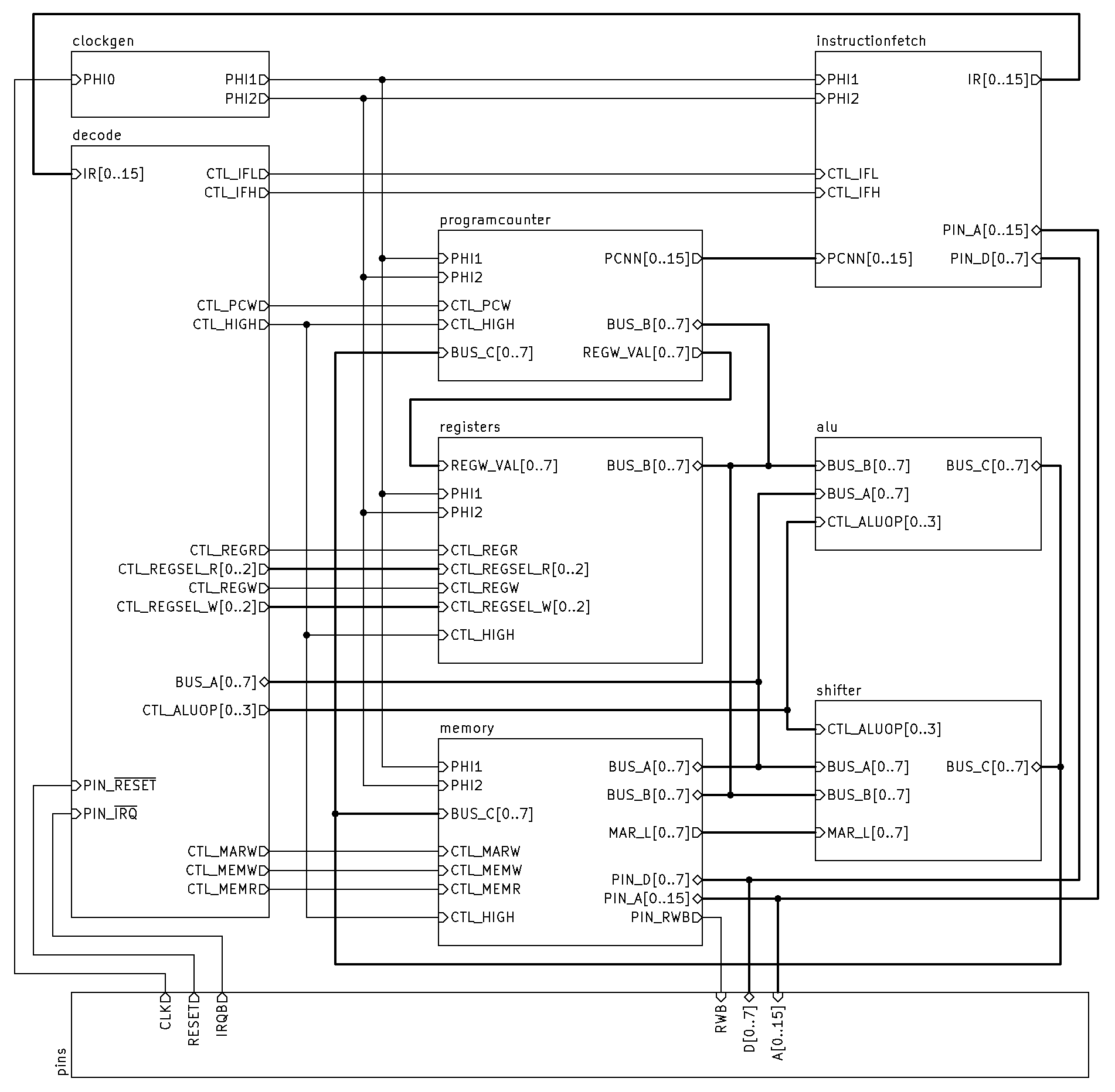
I've been thinking about how to break down the "decode" module from my hardware diagram a bit, into components that might fit into an ATF22V10 or 16V8. I made a Python script that uses my instruction encoder and microcode parser to output VHDL code for the initial phase, that decodes an instruction to determine the microcode address for its first microcode operation - here's the current output: Code: if xir ?= "-----------0---0000" then mcaddr <= "01110111"; -- lui
elsif xir ?= "-----------1---0000" then mcaddr <= "01111001"; -- auipc
elsif xir ?= "-----------0---0001" then mcaddr <= "01111011"; -- addi8
elsif xir ?= "---------0-1--00001" then mcaddr <= "00001000"; -- j
elsif xir ?= "---------0-1--10001" then mcaddr <= "00000100"; -- jal
elsif xir ?= "---------101---0001" then mcaddr <= "01110101"; -- li
elsif xir ?= "---------------0010" then mcaddr <= "01101010"; -- lw
elsif xir ?= "---------------0011" then mcaddr <= "01110001"; -- sw
elsif xir ?= "---------------0100" then mcaddr <= "01100011"; -- lb
elsif xir ?= "---------------0101" then mcaddr <= "01101110"; -- sb
elsif xir ?= "---------------0110" then mcaddr <= "01100111"; -- lbu
elsif xir ?= "-1-000---------0111" then mcaddr <= "10010111"; -- add
elsif xir ?= "-0-000---------0111" then mcaddr <= "10011111"; -- and
elsif xir ?= "-1-001---------0111" then mcaddr <= "10100011"; -- or
elsif xir ?= "-0-001---------0111" then mcaddr <= "10100111"; -- xor
elsif xir ?= "--0010---------0111" then mcaddr <= "10011011"; -- sub
elsif xir ?= "--1010---------0111" then mcaddr <= "11001000"; -- neg
elsif xir ?= "---011---------0111" then mcaddr <= "10111110"; -- sll
elsif xir ?= "---100---------0111" then mcaddr <= "10111010"; -- sra
elsif xir ?= "---101---------0111" then mcaddr <= "10110110"; -- srl
elsif xir ?= "--0110---------0111" then mcaddr <= "10101011"; -- slt
elsif xir ?= "--1110---------0111" then mcaddr <= "11000101"; -- sgtz
elsif xir ?= "--0111---------0111" then mcaddr <= "10110000"; -- sltu
elsif xir ?= "--1111---------0111" then mcaddr <= "11000010"; -- snez
elsif xir ?= "0--------------1000" then mcaddr <= "00101100"; -- beq
elsif xir ?= "1--------------1000" then mcaddr <= "00010100"; -- beqz
elsif xir ?= "0--------------1001" then mcaddr <= "00110100"; -- bne
elsif xir ?= "1--------------1001" then mcaddr <= "00011010"; -- bnez
elsif xir ?= "0---0----------1010" then mcaddr <= "01001000"; -- bge
elsif xir ?= "1---0----------1010" then mcaddr <= "00100110"; -- bgez
elsif xir ?= "0---1----------1010" then mcaddr <= "01011010"; -- bgeu
elsif xir ?= "1---1----------1010" then mcaddr <= "00010000"; -- jr
elsif xir ?= "0---0----------1011" then mcaddr <= "00111111"; -- blt
elsif xir ?= "1---0----------1011" then mcaddr <= "00100000"; -- bltz
elsif xir ?= "0---1----------1011" then mcaddr <= "01010001"; -- bltu
elsif xir ?= "1---1----------1011" then mcaddr <= "00001100"; -- jalr
elsif xir ?= "-----0---------1100" then mcaddr <= "01111101"; -- addi
elsif xir ?= "-----1---------1100" then mcaddr <= "01111111"; -- andi
elsif xir ?= "-----0---------1101" then mcaddr <= "10000001"; -- ori
elsif xir ?= "-----1---------1101" then mcaddr <= "10000011"; -- xori
elsif xir ?= "-----0---------1110" then mcaddr <= "10010001"; -- slti
elsif xir ?= "-----1---------1110" then mcaddr <= "10010100"; -- sltiu
elsif xir ?= "---0-0---------1111" then mcaddr <= "10001101"; -- slli
elsif xir ?= "---0-1---------1111" then mcaddr <= "10001001"; -- srai
elsif xir ?= "---1-0---------1111" then mcaddr <= "10000101"; -- srli
elsif xir ?= "---1-1---000---1111" then mcaddr <= "11010000"; -- ecall
elsif xir ?= "---1-1---010---1111" then mcaddr <= "11011110"; -- rdmepc
elsif xir ?= "---1-1---011---1111" then mcaddr <= "11100000"; -- wrmepc
elsif xir ?= "---1-1---100---1111" then mcaddr <= "11011011"; -- clrmie
elsif xir ?= "---1-1---101---1111" then mcaddr <= "11011000"; -- setmie
elsif xir ?= "---1-1---110---1111" then mcaddr <= "11001100"; -- mret
else mcaddr <= "11111111";
end if;
This is implemented as a series of "if" match statements. I don't know what that would mean in terms of synthesis, but it's fine in simulation. I did see references to, and documentation for, a "case?" instruction that can serve a similar purpose, but it doesn't seem to be implemented in GHDL; and the regular "case" instruction only supports exact matches, without supporting "don't care" bits. It was also easy enough to make some tests in VHDL, e.g.: Code: elsif run("Test JAL") then
ir <= "0000000010010001";
wait for 1 ns;
check_equal(mcaddr, 16#04#);
elsif run("Test ADD") then
ir <= "000" & "010" & "001" & "111" & "0111";
wait for 1 ns;
check_equal(mcaddr, 16#97#);
elsif run("Test AND") then
ir <= "000" & "001" & "010" & "111" & "0111";
wait for 1 ns;
check_equal(mcaddr, 16#9f#);
Concatenating strings of bits seems to be a very easy operation in VHDL, much easier than other ways to achieve the same sort of effect. In the "AND" case, the first three and last four bits are essentially the opcode, and the middle components specify the three registers to use in the operation. The "ADD" case has an identical opcode but the registers must appear in a different order, as we discussed before. To implement this in the decoder, three additional bits are appended to the beginning of the instruction register, to form an "extended" instruction register XIR - these are set or cleared depending on relationships between certain IR bits that are often used to specify registers (6..4, 9..7, 12..10). In instructions where these IR bits are not used for selecting registers - e.g. where they are used as parts of immediate constants, or opcode bits - the extended bits are going to take on fairly random values, but for those instructions the extended bits are "don't cares" for the decoder so this doesn't matter. The work involved in generating the extended bits is a little heavier than I'd like - e.g. a "less than" comparison basically involves performing a three-bit subtraction. It is on the critical path, though, as after the instruction fetch I'll need to perform these subtracts before doing the lookup to determine the microcode address to use for the next cycle. My pipeline only has fetch and execute, there's no separate decoding phase. I do have a solution for this to remove some of the propagation delay, which is to store one of the register operands as a difference from the other one (i.e. do the subtraction at assembly time) - this would allow the instruction decoder to make its decision more quickly, and in the meantime I can add the two register numbers together to get the true value for the second register operand. It costs the same amount but is no longer on the critical path. I won't make any changes there yet though, I'll see how it goes with the existing design first. Aiming towards actual hardware implementation, I'm still hoping to break the system down into pieces that can be implemented in an ATF16V8 or ATF22V10, or in 74-series parts. This stage of decoding feels like about the right size for that - there are a rather high number of input bits (11 from the instruction itself, and 3 extended bits) and 8 output bits, which gives 22 I/O pins in total, just about fitting on an ATF22V10. I made the Python script also generate cupl-format definitions for that, and after doing some product-term reduction, the eight output bits (for the microcode address) still have too many product terms to fit. However, this depends on the actual microcode contents, so there is a lot of wiggle room there to shuffle things around if necessary and hope for a simpler encoding; and also, aligning all the instructions on even boundaries in the microcode would mean these instruction start addresses would all have the low bit set to zero, so only 7 output pins would be required. I checked this and it led to just one of the seven output pins having more product terms than are supported, but since this freed up a whole macrocell for the unused pin, that can now be used internally to combine some of the product terms. The microcode address isn't the only thing I need to get out of the instruction decoder - I also need to know what type of immediate (if any) is encoded in the instruction. I'm planning to do that as a separate lookup either from this initial microcode address, or just as part of the microcode decoding stage that will follow. Speaking of which, I think that's the next step - implementing microcode decoding as a separate module in VHDL. It will have a lot more output signals overall - maybe 20 bits' worth but we'll see - and I think I can just implement it in a very similar way, generating VHDL and then cupl definitions, from Python.
|
| Sun Nov 09, 2025 1:36 pm |
|
Who is online |
Users browsing this forum: byteplus-ai, claudebot, DotBot, SemrushBot and 0 guests |
|
You cannot post new topics in this forum
You cannot reply to topics in this forum
You cannot edit your posts in this forum
You cannot delete your posts in this forum
You cannot post attachments in this forum
|
|